Hardware UX · Research & Fabrication
Designing a steering experience for lunar terrain
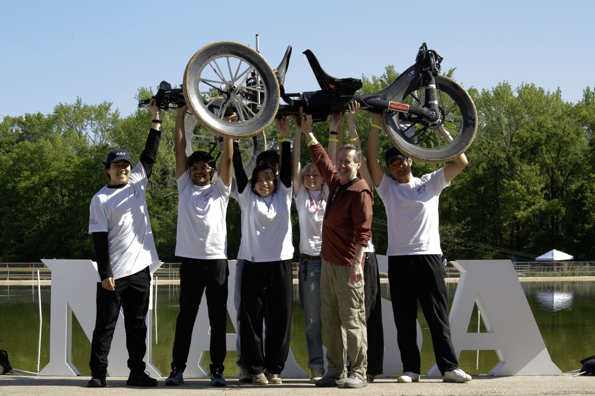
For the 2026 NASA Human Exploration Rover Challenge (Apr 9–11, Huntsville, AL), I led the human-centered process of deciding which steering architecture gave riders the best control, comfort, and confidence on simulated lunar and Martian terrain — then fabricated it.
Role
UX Research Lead (Steering) · Designer & Fabricator
Timeline
Sep–Dec 2025
Team
Wendy Tang · Ray Liu · Adhvik Aggarwal · Raúl Falcón
Tools
SolidWorks · Fusion360 · SLA/FDM · Carbon Fiber
The UX Challenge
Steering as a control experience, not just a mechanism
How might we design a steering system that lets exhausted riders maintain precise control over unpredictable terrain — while preserving comfort, legroom, chassis clearance, and mechanical efficiency?
The drivers had to maneuver through harsh obstacles under physical load, with limited visibility, a confined riding position, and constant suspension movement. The best system wouldn’t just turn the wheels; it would help riders feel stable, confident, and in control.
50°
Target steering angle under extreme driver load
9 ft
Targeted turning radius
94 lb
NASA-mandated maximum vehicle weight
Research · From Sketch to Linkage
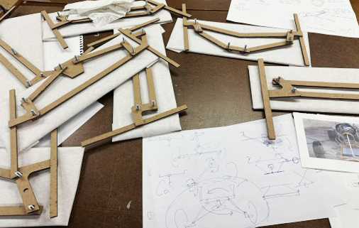
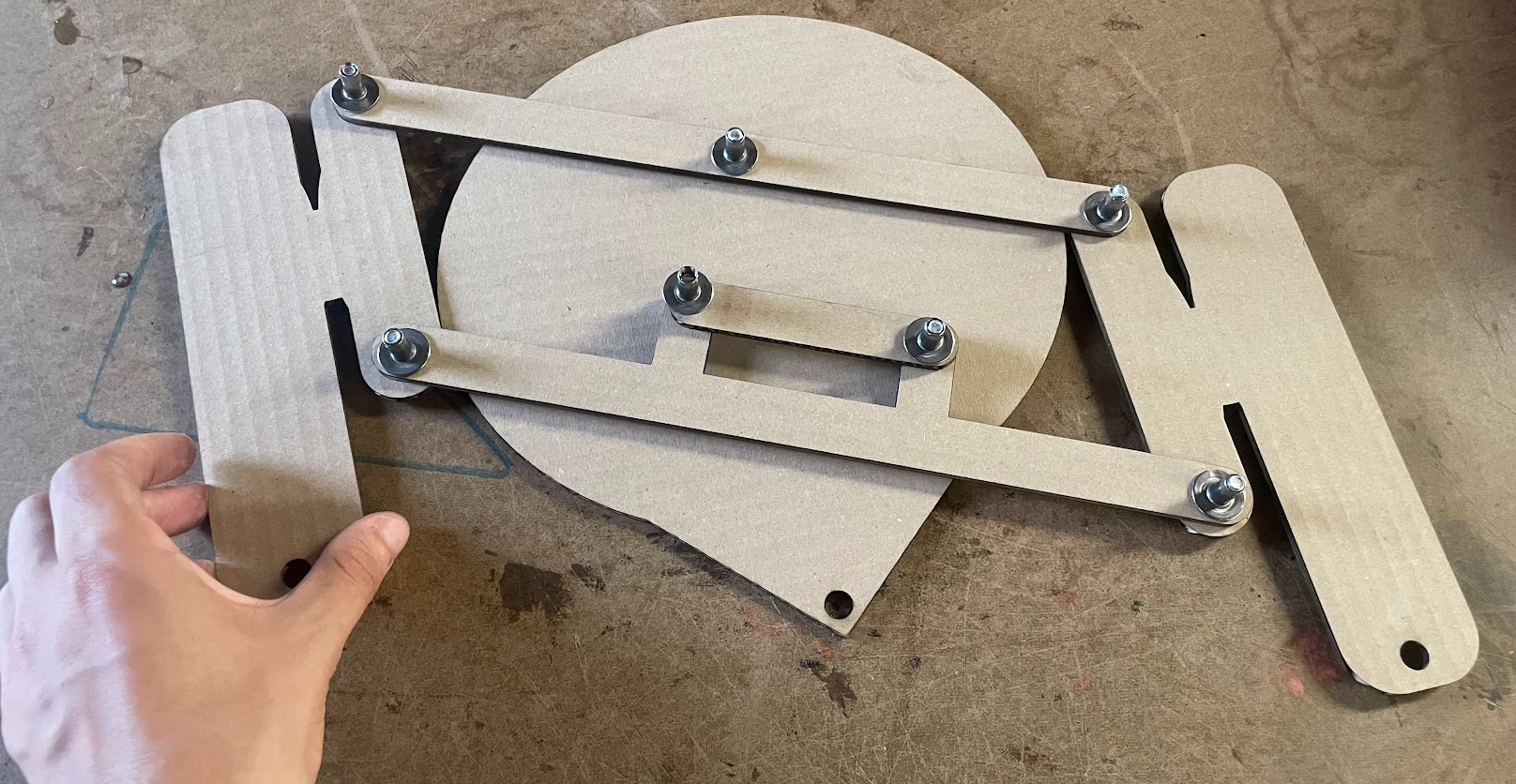
Start cheap, fail fast, learn the motion
Before committing to carbon, we explored the steering motion in pencil and cardboard. Hand sketches mapped how rider input should translate to wheel angle, and low-fidelity four-bar linkages let us feel the geometry and catch problems early — for the cost of a sheet of MDF.
Research · Testing Architectures
Horizontal handlebar vs. Cranker Four-Bar
We compared two steering concepts through prototype testing and rider feedback. The Indirect Bearing (IB) handlebar was instantly familiar — riders understood it immediately and it resisted unintended forces well. But its layout fought our chassis geometry, creating tie-rod offset, packaging conflicts, and bump-steer risk that would make steering less predictable on rough terrain.
The Cranker Four-Bar (C4B) felt less familiar at first, but its perpendicular dual-crank linkage allowed a cleaner tie-rod path and better chassis integration — isolating rider input from terrain feedback for a more consistent, controllable response.
User Testing & Feedback
Familiarity didn’t guarantee better performance
We put both systems in front of riders. The handlebar felt more natural at first, but testing showed the crank reduced packaging conflicts and gave a more controllable, terrain-ready steering path. This footage is the central artifact behind the design decision.
01
Familiar ≠ better
Riders adapted to the handlebar instantly, but familiarity alone didn’t produce the most controllable steering.
02
Fewer conflicts
The crank reduced tie-rod offset and packaging conflicts, smoothing the steering path over obstacles.
03
Confidence over terrain
Feedback helped us balance intuitiveness, control, clearance, and confidence under load.
The Decision
A UX decision matrix, not a mechanical preference
We chose the C4B not because it was mechanically cooler, but because it delivered the strongest total experience under competition constraints — predictable response, reduced chassis interference, and room to evolve around the rider.
| UX Criteria | Horizontal Handlebar / IB | Cranker Four-Bar / C4B |
|---|---|---|
| Familiarity | Strong — similar to bike/trike steering | Moderate — required rider adaptation |
| Sturdiness | Strong — resisted unintended rider forces | Moderate — vertical handlebar more exposed |
| Packaging | Weak — chassis geometry caused tie-rod offset | Strong — cleaner linkage path |
| Rough-terrain control | Weaker — bump-steer risk | Stronger — more consistent turn response |
| Leg clearance | Constrained by chassis and rider position | Improved through later iterations |
| Final UX fit | Familiar but mechanically compromised | Less familiar, but more controllable and terrain-ready |
Final direction
Cranker Four-Bar Steering System
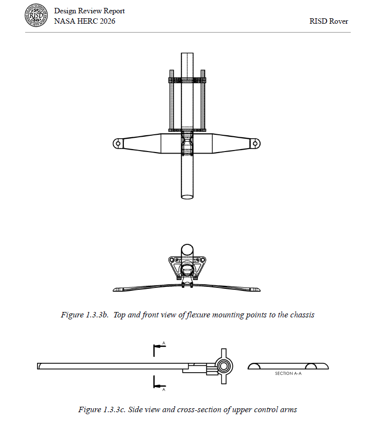
Iteration · Designing Around the Rider
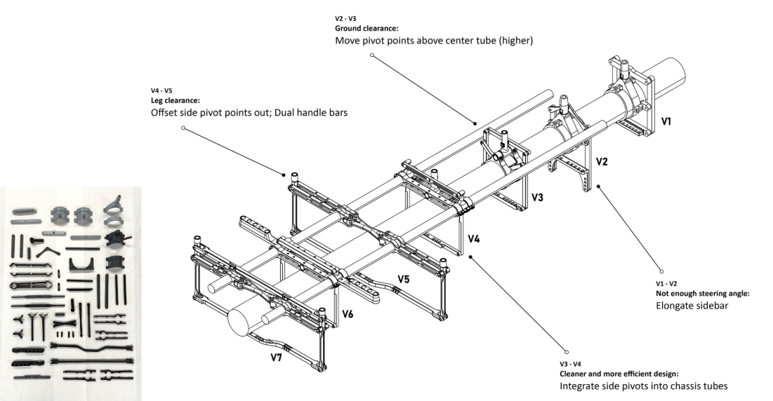
Seven versions, each solving a real rider problem
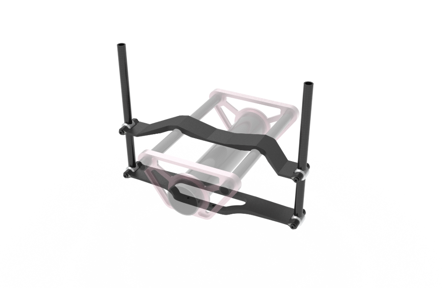
Between Version 1 and Version 7, the geometry was entirely overhauled. Each iteration responded to a specific user or terrain problem — turning the steering into an ergonomic interface between rider, chassis, and terrain.
01
V1–V2 · Steering angle
Elongated the sidebars to widen the steering range and tighten the turning radius.
02
V2–V3 · Ground clearance
Shifted pivot points above the center tube so the mechanism wouldn’t strike obstacles during suspension travel.
03
V4–V5 · Leg clearance
Offset side pivots outward and added dual handlebars to keep clear of the drivers’ legs.
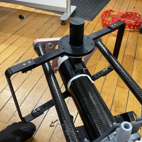
Fabrication · Built for Feel
Lighter, smoother, stronger — for the rider
Once the C4B was validated, I helped translate it into a lightweight, durable assembly. Every fabrication choice mapped back to the rider experience: less fatigue, more predictable steering, better reliability during competition.
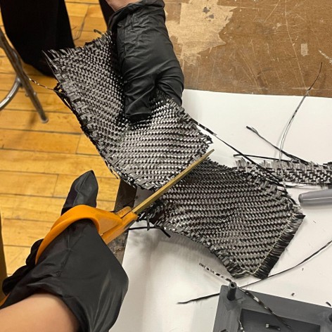
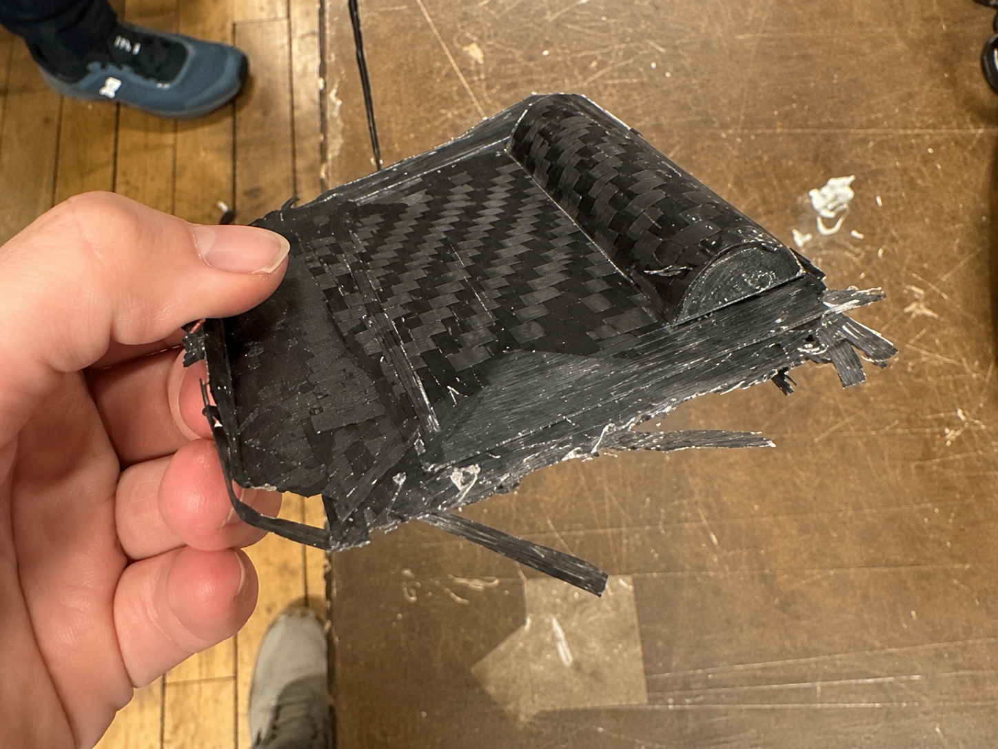
01
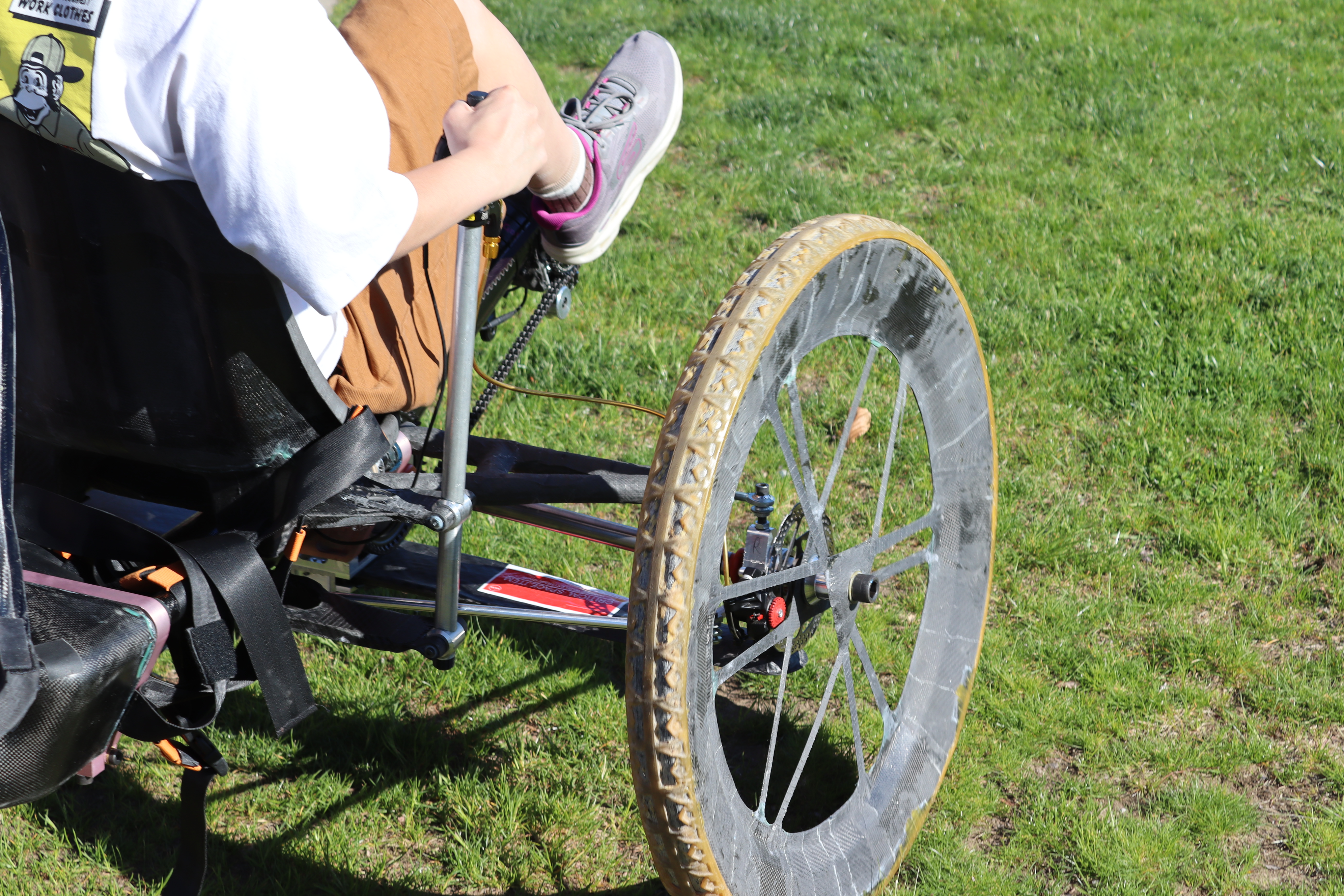
Carbon fiber linkages
Thin-walled carbon tubing cut weight while preserving rigidity — less mass for the rider to fight.
02
3D-printed internal supports
LW-PLA inserts embedded in wet layups reinforced high-stress joints for durability.
03
Low-friction bushings
SLS-printed bushings and shoulder bolts kept actuation smooth under heavy rider load.
Documentation & Technical Storytelling
Communicating the decision
I served as technical editor for the steering section of our 100+ page NASA Design Review — translating prototype results and tradeoffs into a clear narrative for NASA reviewers, with rigorous citation accuracy for safety review.
NASA Phoenix Award · Greatest improvement between reports
Our documentation earned the NASA Phoenix Award for the greatest improvement between reports.
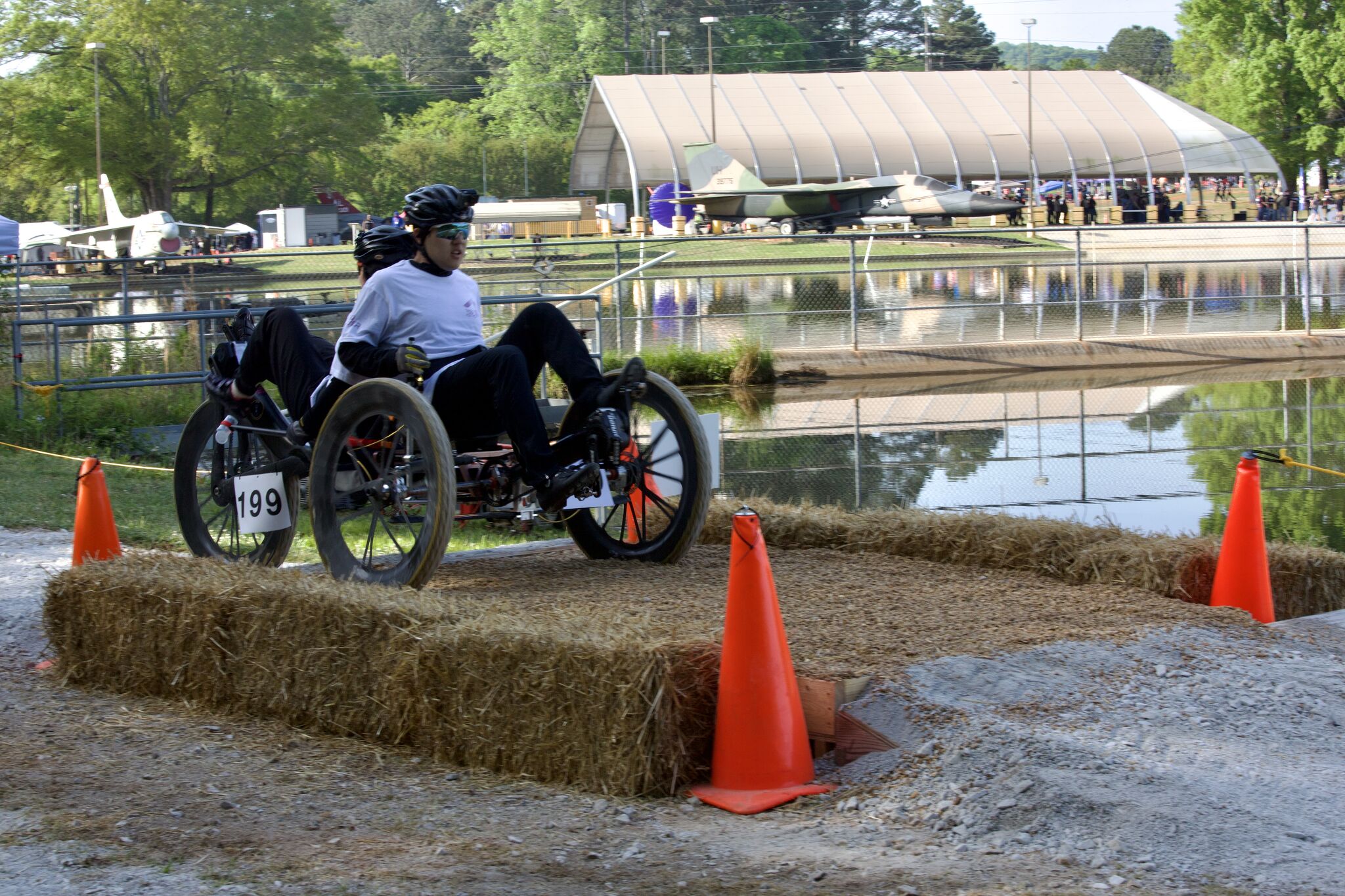
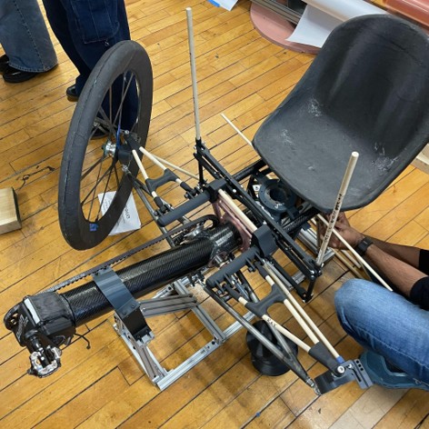
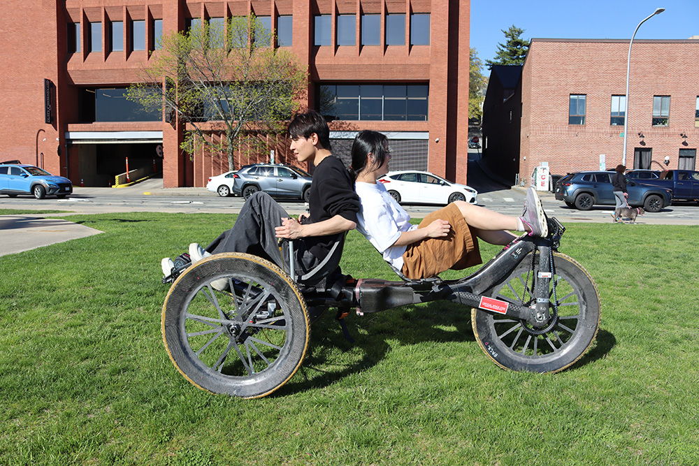
Validation · Real Riders
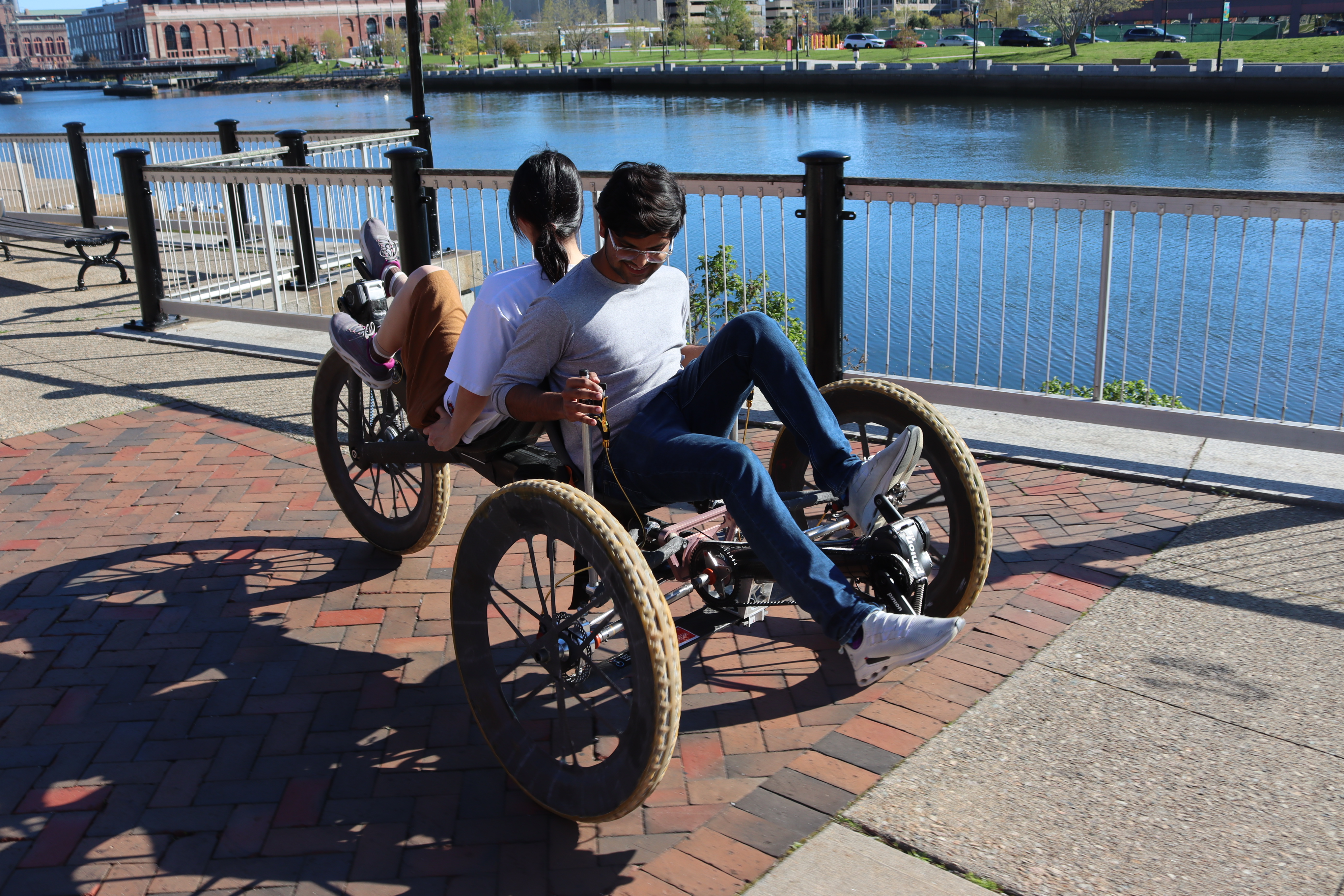
Putting real bodies on the final build
The truest test of a steering UX is people actually riding it. We put teammates of different heights and builds on the finished rover — confirming the seating position, leg clearance, and steering reach worked for real riders, not just the CAD model.
01
Fits real bodies
Cockpit, legroom, and reach validated across riders of different heights and builds.
02
Confident control
Riders kept a stable, predictable hold on the crank while pedaling under load.
03
Ready for terrain
Clean tracking on flat ground translated to composure over obstacles at the challenge.
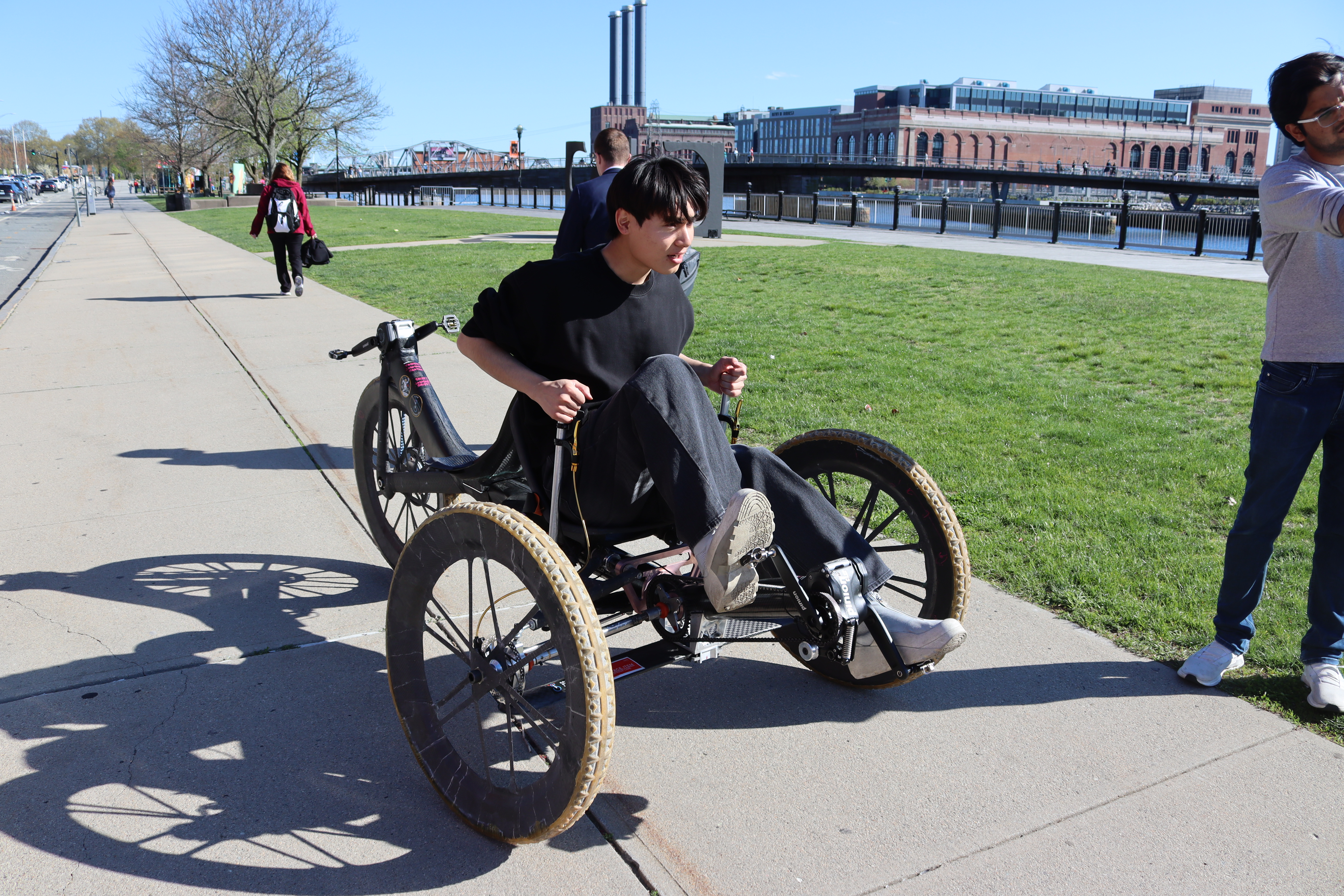
Outcome
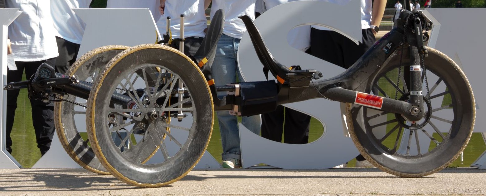
A steering system designed around the rider
The final Cranker Four-Bar system turned CAD exploration into a race-ready carbon-fiber assembly on the RISD Rover chassis — selected by testing architectures, listening to riders, and iterating around real ergonomic constraints.
Next project
CurioXR